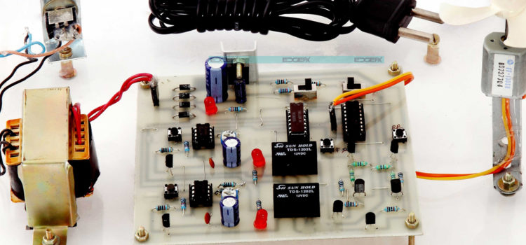
The speed of DC motor can be varied by applying various techniques. The drive system comprising the drive and the DC motor is vital to speed control in DC motor.
This is to regulate the amount of energy produced by the machine and the amount of work required to be done by the system at a given time duration.

DC Motors And Drives
The DC drive is a simple device that regulates the amount of electrical current sent to a DC motor. It supplies electrical energy in varying frequencies and quantities, hence controlling the speed of the electric motor.
The use of DC motor is increasingly growing in the metal industries, in mining, printing and in crane implementation. Though the current trend is the replacement of DC motors with more efficient AC drives, the task of getting this implemented is however not time and cost effective. Using the existing motor and improving on the drive is often the best option for industries.
DC drives provide great benefits to the DC motor such as control techniques, improved motor performance, system integration and reliability of the drive system which is a key component of DC motor speed control.

Speed Control Without Microcontroller
Designing and developing a circuit without a microcontroller integrated into it lowers costs and other downsides like the limited range in the circuit design.
Methods
The speed of a DC motor can be varied by means of mechanical or electrical methods. The use of a microcontroller for speed control is gradually fading away. The disadvantage of utilizing a microcontroller in system design is the somewhat large size of the implementation.
Using Direction Control And Microprocessors
Without using microcontroller, speed control can be achieved through direction control. This is done by reversing the input voltage terminals of the motor to have the required output of energy. Two-wheeler designs are often used to implement this method. Microprocessors are other devices used to achieve speed control in a DC motor.
In this approach, sensing the current and terminal voltage is implemented. This results in comparing the reference speed of the motor to its actual speed to generate an appropriate control signal which goes into the triggering unit to cause a required output.
Pulse Width Modulation Method
PWM (Pulse Width Modulation) is a technique for producing an analog signal using a digital source. A Pulse Width Modulation signal is made up of two components namely; the frequency and the duty circle. These describe the behavior of the signal.
The duty circle defines the quantity of time the signal is in ON (high) state. It is shown as a percentage of the period it takes to make a complete circle.
The frequency of the signal defines how fast a complete circle is completed by the PWM and hence how fast it switches between Low and High states. By cycling a signal at Low and High state at a fast rate with the specified amount of duty circle, the output’s behaviors can be compared to be a frequent voltage analog signal when sending energy to devices.
Pulse Width Modulation refers to the process of varying the duty cycle. This reduces the terminal voltage with a heat loss. 555 timer can be used to implement this technique. Double Pole Double Through (DPDT) switch can be used to change the direction of the voltage. A semiconductor-type H-bridge is preferable to implement this aspect of the design on speed regulation.
 Factors Affecting The Speed Of Dc Motor
The operation of a DC motor is typically designed such that when a current carrying conductor is placed within a magnetic field, there is bound to be the mechanical force that goes through the conductors. A permanent magnetic DC motor, however, does not have field circuit. It has just the armature circuit. This differentiates it from other DC motors.
The factors affecting DC control are therefore:
- The applied voltage
- The flux
- The voltage across an armature
Considering these factors, speed control can then be achieved through the following techniques:
- Flux control method: This is done by varying the current via the field winding, thus altering the flux.
- Rheostatic control: changing the armature route resistance which also changes the applied voltage across the armature.
- Voltage method: changing the applied voltage


