Reading a Panel's Timing on a Scope
A sync pulse and a pixel clock carry more truth about a display's refresh behaviour than any spec sheet entry — if you know what to look for.
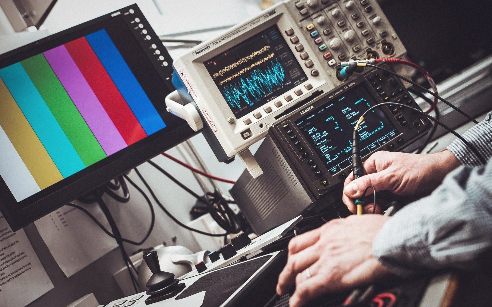
What the Signals Tell You
Every display interface — HDMI, DisplayPort, LVDS, eDP — encodes the same fundamental timing structure: a pixel clock, horizontal sync (Hsync), vertical sync (Vsync), and blanking intervals that separate active video from the overhead the controller needs to reset. The nominal refresh rate you read on the box is derived from these four elements by simple arithmetic: divide the pixel clock frequency by the product of the total horizontal pixel count (active plus blanking) and the total vertical line count (active plus blanking), and the result is the frame rate. Scoping those signals lets you verify whether the hardware is actually delivering that arithmetic — and whether the blanking widths match the VESA, JEDEC, or MIPI DSI timing spec the panel vendor claimed.
A basic four-channel digital storage oscilloscope, 200 MHz bandwidth or better, is sufficient for LVDS and eDP signals on the connector side of the TCON. Probe the Hsync and Vsync lines with 10× passive probes, set the timebase to capture two or three complete Vsync cycles, and trigger on the falling edge of Vsync. The interval between falling edges is your real frame period. Divide one second by that period and you have the actual refresh rate, independent of what the GPU reports. A panel nominally at 120 Hz that measures 8.47 ms per frame is running at 118.1 Hz — a discrepancy that shows up immediately and that no software tool will tell you, because the OS trusts the EDID.
Blanking, Pixel Clock, and What Hides in the Margins
Horizontal blanking is where the noise lives. The front porch (time between end of active video and Hsync assertion), sync width, and back porch each have minimum values defined in the timing standard; violate them and the TCON misbehaves, usually producing instability at the top of frame or during mode transitions. Scope the Hsync against a pixel-clock-derived reference and you can measure each interval in nanoseconds, then compare directly to the datasheet. Panels that ship with margins cut to the absolute minimum to hit a higher refresh rate often exhibit exactly this failure mode — the timing is technically within spec at room temperature, then drifts out when the TCON warms up.
The pixel clock itself deserves its own channel. Route a clock-derived signal from the spread-spectrum clock generator or the serialiser reference output and measure frequency drift over a ten-minute warm-up. Spread-spectrum clocking — standard practice for EMI compliance — modulates the pixel clock across a small frequency range, typically ±0.5 % around the centre frequency. That modulation is visible as a sinusoidal frequency variation on a frequency-vs-time display, and its presence explains why a pixel-clock measurement averaged over a short window can look perfectly stable while individual frame periods jitter. A histogram of frame periods, sampled over hundreds of Vsync intervals, reveals that jitter distribution and its standard deviation — a number that translates directly to variable refresh rate stability and perceived frame-pacing consistency.
Blanking intervals also encode the control signals that switch a panel into and out of local dimming modes or trigger backlight strobing: look for narrow auxiliary pulses riding in the vertical blanking interval. These are usually proprietary to the panel vendor, but their timing relative to Vsync — setup time, pulse width, hold time — determines whether the backlight event aligns with the correct frame or slips by one, which is exactly the artefact that manifests as a one-frame luminance error in bright scenes.